Grounding for Screened and Shielded Network Cabling
Shielded cabling, of one type or another, has been the preferred cabling infrastructure in many global markets for many years. Cables described as foil screened unshielded twisted-pair (F/UTP) and fully shielded cables with an overall braid screen plus individual foil shielded twisted pairs (S/FTP) are now gaining popularity in markets where unshielded twisted-pair (UTP) cabling has traditionally been the most common solution.

This rise in adoption is tied to the publication of the IEEE standard known as 802.3an 10GBASE-T and this emerging application’s sensitivity to noise from adjacent cabling. This noise from adjacent cabling is known as alien crosstalk. Screened and fully shielded 10 Gb/s cabling systems, such as category 6A F/UTP and category 7 S/FTP, are all but immune to the alien crosstalk that presents problems for category 6A UTP cabling. These cabling systems can help reduce the size and cost of pathway spaces due to their smaller diameters..
Even as cabling installers and their clients increasingly enjoy these benefits, confusion surrounding the bonding and grounding of screened and shielded systems has caused some to avoid them. This concern is unfounded, as advances in screened and shielded cabling systems have simplified bonding and grounding methods tremendously. Today, the installation and bonding and grounding/earthing of F/UTP and S/FTP cabling systems requires little additional effort and expertise over UTP installations.
Why Bond and Ground?
While electrical services, telecommunications equipment, and all other low voltage systems are required to be bonded to ground per national and local electrical codes and industry standards for safety reasons; the specific need to ground screened and shielded network cabling systems is only a matter of performance. A properly bonded and grounded cabling system carries noise currents induced by electromagnetic interference (EMI) in the environment to ground along the screen or foil shield, thereby protecting the data-carrying conductors from external noise. The screen or foil shield also minimizes cabling emissions. It is these functions that afford screened and shielded systems their superior immunity to alien crosstalk and other sources of conducted or radiated electromagnetic interference.
S/FTP and F/UTP vs. UTP – How does the Need to Ground Effect Installation Practices?
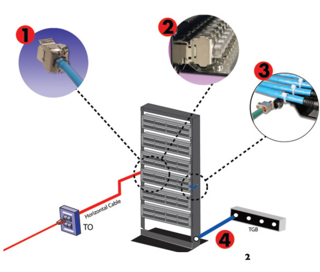
The recommended grounding sequence is as follows: the , the outlet self-grounds to the patch panel, and then the panel is grounded to the equipment rack or adjacent metallic pathways. The basic sequence is reflected in the diagram below.

- F/UTP cables screen or the S/FTP shield is terminated by the outlet
- Outlet makes contact with patch panel’s grounding strip as outlets are snapped into place
- Panel is grounded to equipment rack or adjacent metal pathways via a 12 AWG wire attached to panel ground lug
- 6 AWG ground wire connects rack to the TGB
Where From Here?
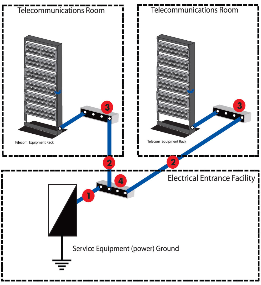
The continuation of ground path from the equipment rack or adjacent metallic raceway to the TGB now falls under the broader requirements of the telecommunications network grounding system. It is critical to note that the grounding steps dictated by the applicable codes and standards are the same for UTP, F/UTP and S/FTP cabling systems. Although standards and codes differ from region to region and country to country, the methodology for properly grounding the telecommunication network is largely equivalent. To understand the process, a few definitions are required. The following are taken from ANSI-J-STD-607-A and illustrated in the diagram below:

Bonding: The permanent joining of metallic parts to form an electrically conductive path that will assure electrical continuity and the capacity to conduct safely any current likely to be imposed. To expand on the ANSI definition, electrical bonding is a process in which components or modules of an assembly, equipment or subsystems are electrically connected by means of a low-impedance conductor. Bonding purpose is to make the shield structure homogeneous in regards to the flow of RF currents. Bonding can be achieved by different methods as follows:
a) by metallic interfaces through fasteners or by direct metal-to-metal contact
b) joining two metallic parts or surfaces through the process of welding or brazing
c) by bridging two metallic surfaces with a metallic bond strap
- Bonding conductor for telecommunications: A conductor that interconnects the telecommunications bonding infrastructure to the building’s service equipment (power) ground.
- Telecommunications bonding backbone: A conductor that interconnects the telecommunications main grounding busbar (TMGB) to the telecommunications grounding busbar (TGB).
- Telecommunications grounding busbar: The interface to the building telecommunications grounding system generally located in telecommunications room. A common point of connection for telecommunications system and equipment bonding to ground, and located in the telecommunications room or equipment room.
- Telecommunications main grounding busbar: A busbar placed in a convenient and accessible location and bonded by means of the bonding conductor for telecommunications to the building service equipment (power) ground.
The procedures for bonding and grounding a telecommunications network are straightforward. The cabling system and equipment is grounded to equipment racks or adjacent metallic pathways. These are in turn connected to the TGB. The TGB is bonded to the telecommunications main grounding busbar (TMGB) via the telecommunications bonding backbone. Finally, the TMGB is connected to the main service ground by the bonding connector for telecommunications. Although actual methods, materials and appropriate specifications for each of the components in the telecommunications bonding and grounding system vary according to system and network size, capacity and by local codes, the basic structure remains as illustrated above. From the rack to earth, the process is the same for a UTP, F/UTP or S/FTP cabling infrastructure.
Final Thought
If your facility’s bonding and grounding system complies with safety codes, then it more than satisfies the bonding and grounding requirements for the proper performance of any twisted-pair cabling system. All that is required to realize the performance benefits of F/UTP and S/FTP cabling is the addition of a low impedance connection from the patch panel in the telecommunications room (TR) to the rack, which should already be connected to the TGB. Ensure that the facility’s bonding and grounding system protects the people who use it and any concerns associated with the addition of a screened or shielded cabling system will be eliminated.
Rev. F 8/13


