Cable Sharing in Commercial Building Environments:
Reducing Cost, Simplifying Cable Management, and Converging Applications onto Twisted-Pair Media
Cable sharing describes the practice of running more than one application over different pairs of a balanced twisted-pair copper telecommunications channel. Common examples of cable sharing include transmitting twelve 10BASE-T lines over one 25-pair cable and using y-adapters to break out separate voice and fax lines transmitting over one channel. Although the concept of cable sharing is clearly accepted by telecommunications professionals, it is only now starting to become a recognized practice for reducing costs, simplifying cable management, and converging applications onto one media type in commercial building environments. The growing market acceptance of fully-shielded (i.e. “category 7A” or “class FA”) cabling systems has been identified as the primary reason why cable sharing techniques are appearing in the designs of the industry’s top IT infrastructure designers and consultants.
TIA1 and ISO2 Telecommunications Standards specify generic topologies and minimum recommendations to ensure consistent cabling system design throughout the world. In many commercial environments, the minimum Standards’ requirement 3 to provide two telecommunications outlets at each work area is adopted as the basic building infrastructure design. However, there are some end-user environments, such as call centers, fax centers, classrooms, training centers, and monitoring facilities that are supporting significantly more than two applications at each work area. In fact, some patient recovery room designs facilitate a minimum of 15 applications4 at each work area! As shown in table 1, these high-density work areas are typically supporting multiple low-speed applications in addition to one high-speed data service. Cable sharing strategies benefit these types of work areas by simplifying cable management through decreased cable count and reducing waste and cost by eliminating the unused pairs that would be present if a 4-pair channel was dedicated to each application. Further cost and cable management benefits can be realized if services such as CATV and CCTV, that typically transmit over coaxial cable, and intercom, that transmits over 18 AWG copper wires, are converged onto the telecommunications network using low-cost media converters such as baluns.
| Analog Voice | 1-Pair |
| VoIP | 2-Pair |
| Video over IP | 2-Pair |
| CATV | 1-Pair w/balun |
| CCTV | 1-Pair w/balun |
| 10/100BASE-T | 2-Pair |
Table 1: Typical Applications in High-Density Work Area Environments
Some designers and consultants are still concerned about specifying cable sharing because they are unsure of the Standards’ acceptance of the practice. The good news is that both TIA and ISO recognize and provide guidance on cable sharing implementation. TIA TSB-1905 describes the transmission performance of various types of applications that do not interfere with each other in a shared environment based upon the internal crosstalk found in UTP (unshielded twisted-pair) cabling systems and provides examples of applications that can coexist in multipair cables. The Standard also indicates that knowledge of an application’s transmission type (i.e. bursty, continuous, synchronized or random) and the internal noise of the cabling plant can be used to make a determination as to whether multiple applications or appearances of the same application can coexist in one channel. The ISO/IEC 11801: 2002, 2nd edition Standard expands on this information and provides crosstalk considerations for cable sharing and guidance for minimizing sheath-sharing incompatibilities. The ISO/IEC 150186 Standard goes one step further and recommends that cable sharing may be considered when pathway space is limited in residential environments. Industry groups such as BICSI 7 and building codes such as the NEC®8 in the United States accept the practice of cable sharing. In summary, all telecommunications standards recognize cable sharing and provide implementation guidance based upon the potential for application interference due to the internal crosstalk levels of the cabling channel.
Cable sharing did not start gaining in popularity until the adoption of fully-shielded (i.e. class F and FA) cabling systems by the ISO Standard. This is because the amount of internal crosstalk coupling (both near-end and far-end) in UTP and F/UTP (foil over twisted-pair) cabling systems made it difficult for users to predict whether multiple applications could coexist in one cable. As shown in figures 1 and 2, calculations demonstrate that 23.4% of an application’s transmitted signal appears as either power sum near-end or far-end crosstalk noise at 100 MHz in category 5e/class D cabling systems. The situation improves for category 6A/class EA systems, with 11.4% of an application’s transmitted signal appearing as either power sum near-end or farend crosstalk noise at 100 MHz, but this performance is not sufficient to ensure that all applications will perform properly in a shared sheath environment. With only 0.7% of an application’s transmitted signal appearing as either power sum near-end or far-end crosstalk noise at 100 MHz, end-users are guaranteed that there is sufficient noise isolation between pairs to support multiple applications or the multiple appearance of any one application over a 4-pair class FA channel.
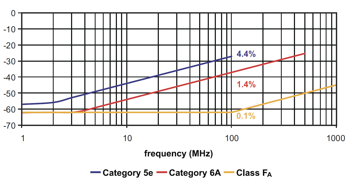
Figure 1: Comparative Channel PSNEXT Loss Coupling
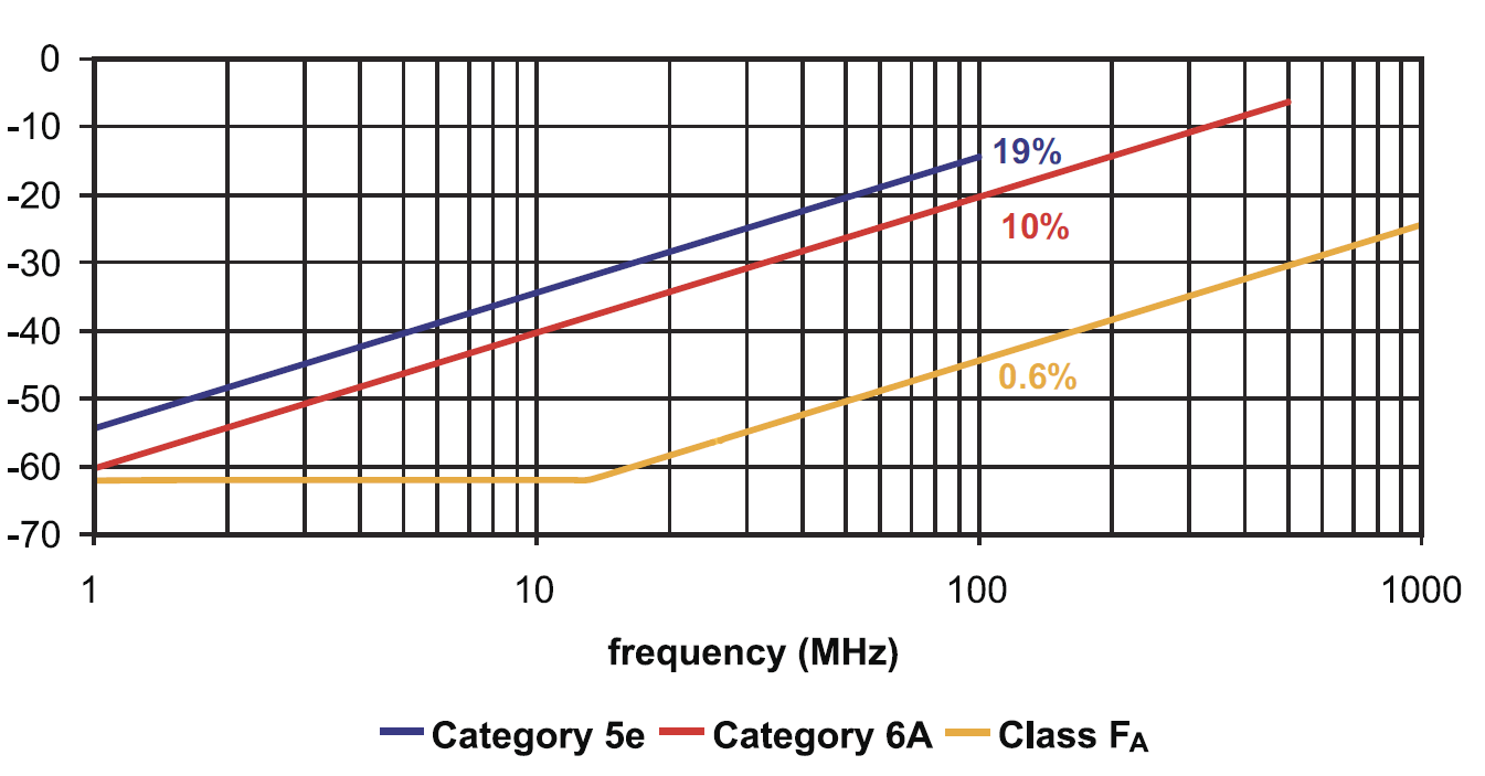
Figure 2: Comparative Channel PSACRF Coupling
Class FA cabling requirements are specified in amendment 1 to ISO/IEC 11801:2002, 2nd Edition and represent an extension of the class F cabling requirements originally published in 1999. While class F cabling still exists today, class FA cabling is characterized over the extended bandwidth of 1 MHz to 1,000 MHz, which makes it ideal for supporting all channels of CATV (up to 698 MHz), and is the fully-shielded media of choice. Class FA channels are constructed from fully-shielded category 7A cable and the preferred category 7A connecting hardware interface for cable sharing implementations is the non-RJ style interface described in IEC 61073-3-104 and shown in (figure 3). This is because the isolated quadrant design of the non-RJ style interface allows easy access to one or two pairs of the channel using 1- and 2-pair non-RJ style plugs terminated to appropriately wired RJ-45 or RJ-11 Ethernet plugs as shown in (figure 4).
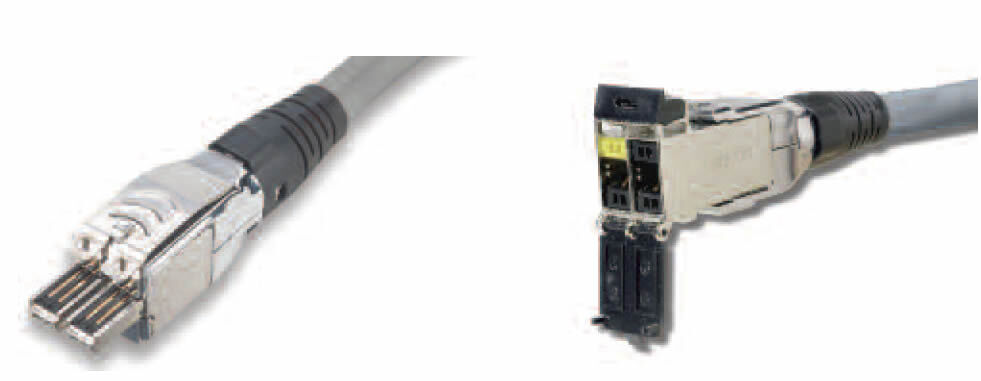
Figure 3: Siemon TERA® Connector is an Example of a
Non-RJ Plug and Jack Interface
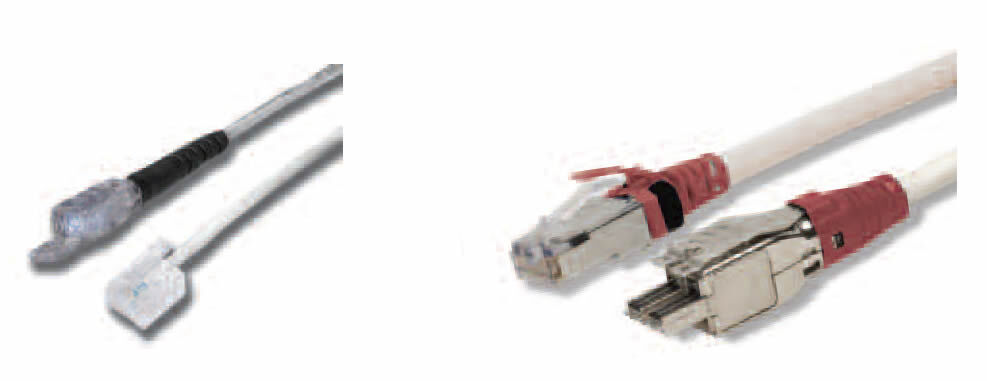
Figure 4: Hybrid Cords (1-Pair Non-RJ Style Plug-to-RJ11
and 2-Pair Non-RJ Style Plug-to-RJ45 Plug)
Although cable sharing implementation practices are extremely flexible and support a wide range of configurations, two basic configurations can satisfy the needs of most end users. In call and fax centers, agents are typically arranged in work groups and are supported by both an analog phone and Internet connection. In this example, the recommended cable-sharing practice would be to provide each work group of 4 agents with a MuTOA9 containing one category 7A outlet and four category 6A outlets. The one class FA channel would provide 4 analog phone lines to the group as shown in figure 5. By utilizing cable sharing practices in call and fax centers, end-users typically realize a cost savings in excess of 10% for materials, a 38% reduction in the total number of outlets, and reduced cable management complexity. In many multiapplication environments, such as classrooms, healthcare, and monitoring facilities, work area outlets support a plethora of services including VoIP (voice over IP), CATV, CCTV, Internet, security cameras, intercom, and high-speed data. In this example, providing a dedicated cable for each application would require 9 outlets at the work area! A more efficient solution for multi-application environments such as this is to implement cable sharing whereby each work area would support the 9 services over two class FA channels and one category 6A channel. The two category 7A outlets would support the services depicted in figure 6. Using this implementation, end-users typically realize a cost savings in excess of 20% for materials, a 57% reduction in the number of outlets, and reduced cable management complexity. In addition, these end-users benefit from converging their coaxial (CATV and CCTV) and copper wiring (intercom) onto the telecommunications network for the added benefit of simplified infrastructure management and reduced complexity.
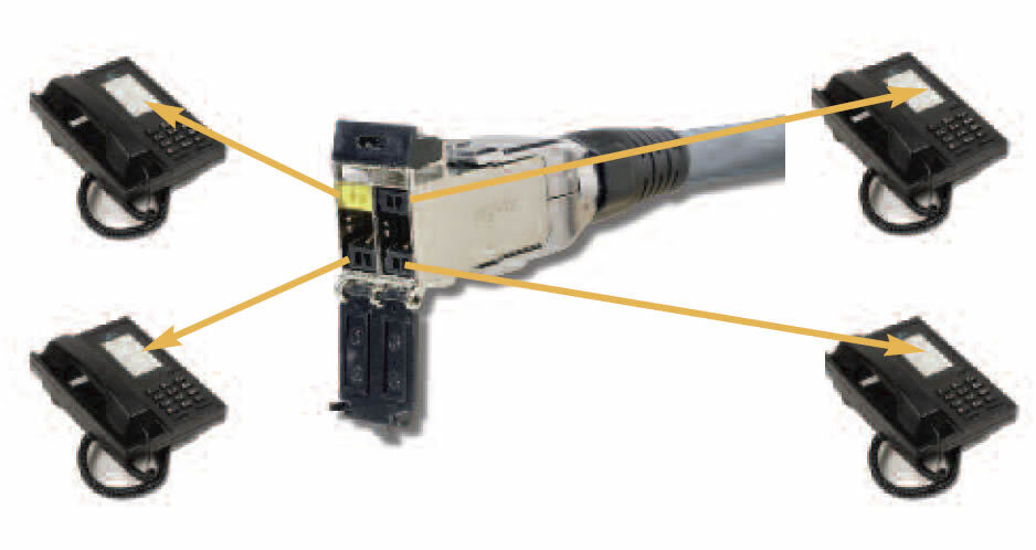
Figure 5: Typical Call/Fax Center Cable Sharing Implementation
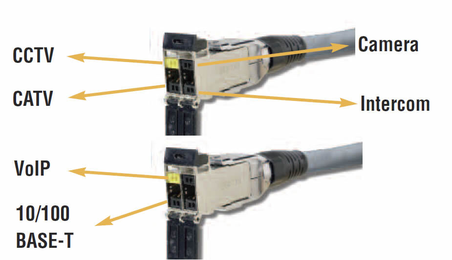
Figure 6: Typical Multi-Application Cable Sharing Implementation
When designing cable sharing solutions, it is critical to plan for the types of applications to be supported and understand their equipment lifecycles. Fortunately, the lifecycle of call center and most video applications is greater than the 10-year life cycle specified by the TIA and ISO Standards for data applications. Although there are many benefits to be realized from implementing cable sharing design strategies, it is important to remember that these techniques can reduce the ability of the cabling infrastructure to support future applications and upgrades.
As a result, the recommended practice for all cable sharing solutions is to provide a minimum of one dedicated 4-pair category 6A or higher rated outlet in addition to the shared category 7A outlets to ensure a migration path for high-speed data upgrades. End-user demand for high-density, lowspeed application support is increasing as more and more equipment devices support IP protocol, Ethernet communication, and operation over twisted-pair cabling. Fortunately, class FA cabling provides the necessary internal noise isolation to support Standards-approved cable sharing methods that reduce cost, simplify cable management, and support convergence of applications on twisted-pair media.
Footnotes:
1 TIA is the acronym for the Telecommunications Industry Association
2 ISO is the acronym for the Internal Standards Organization
3 Minimum telecommunications outlet requirements are specified in ANSI/TIA-568-C.1 and ISO/IEC 11801: 2002, 2nd edition
4 Typical applications supported include: 2 voice, 4 clinical Ethernet data, 2 ICU remote patient monitoring Ethernet data, 1 nurse-call Ethernet, 1 auxiliary Ethernet data for non-clinical applications, 2 patient entertainment, and additional outlets for “family zone” activity
5 TIA TSB-190, “Guidelines on Shared Pathways and Shared Sheaths”, June 2011
6 ISO/IEC 15018, “Information Technology – Generic Cabling for Homes”, April 2009
7 See www.bicsi.org for more information
8 NEC is the acronym for the National Electrical Code®
9 MuTOA is the acronym for Multi-user Telecommunications Outlet Assembly WP_CableSharing_ Rev. D


