A Closer Look at Fiber Optic Cable Assemblies
Many network performance problems occurring at the physical layer are directly related to cable assembly quality. In fact, the overall performance and reliability of a network port is only as good as the cabling to which it is connected. This is particularly true of optical fiber cable assemblies, where seemingly minute variances in tight fiber connectivity tolerances can drastically undermine cabling performance. While a percentage of assembly performance issues may be identified through field testing of installed channels, field testing is not inclusive of all potential issues. Although a critical step, field testing can provide a false sense of security. For example, a single passing result for insertion loss does not guaranty long term reliability.
To help network infrastructure professionals understand the variables affecting the quality of fiber assemblies, Siemon has performed comprehensive benchmark testing on a representative assortment of commercially available fiber assemblies. The study included generic fiber jumpers purchased through on-line retailers that were produced by both domestic (US) and offshore assembly houses as well as assemblies from Siemon and other globally known brands – all purchased through authorized distributors. This benchmark testing provides a detailed review of mechanical and optical characteristics that are critical to the performance and longevity of these connections.
Testing was performed on 36 random samples of duplex LC laser optimized multimode OM3 50/125 fiber jumpers from 9 suppliers – Siemon, 4 other leading global manufacturers and 4 generic assembly houses. We tested each assembly to Siemon Internal specifications as well as TIA and IEC standards for end face geometry, optical performance, cleanliness and mechanical reliability. Every Siemon XGLO and LightSystem product is 100% tested and inspected for end face geometry, cleanliness, surface defects, insertion loss and return loss (both directions and both wavelengths). Each jumper is serialized and traceable to factory test results for insertion loss and return loss.
Optical Performance
Insertion loss and return loss performance are fundamental parameters used to assess the compatibility of optical fiber links and channels with the specific networking applications they support. Insertion loss is commonly used as the basis for acceptance testing of installed links and channels. Although return loss testing of installed cabling is not required by industry standards, it is a normative requirement for fiber connectors and assemblies. Return loss is critical to optical performance of links and channels because reflected optical signals can interfere with detectors on both the forward and rearward directions. These reflections degrade signal to noise ratio and are commonly presented using “eye diagrams”, with higher return loss resulting in a smaller eye opening (height, peak to peak). Likewise, testing in both directions and at both wavelengths will detect abnormalities that degrade optical performance of cabling channels.
Table 1: Insertion Loss and Return Loss Test Results:
Insertion Loss – 1 out of 9 manufacturers had 1 or more failures.
Return Loss – 3 out of 9 manufacturers had 1 or more failures
|
|
Industry Standard ISO/IEC 11801 Ed. 2.2; TIA/EIA 568C.3 |
Siemon Specification |
||
|
Manufacturer |
IL (.75 dB) |
RL (20dB) |
IL (.25 dB) |
RL (30dB) |
|
Siemon |
Pass |
Pass |
Pass |
Pass |
|
1-Global MFG |
Pass |
Pass |
Pass |
Pass |
|
2-Global MFG |
Pass |
Pass |
Pass |
Pass |
|
3-Global MFG |
Pass |
Pass |
Pass |
Pass |
|
4-Global MFG |
Pass |
Pass |
Pass |
Pass |
|
5-Generic |
Pass |
Fail |
Pass |
Fail |
|
6-Generic |
Pass |
Pass |
Pass |
Pass |
|
7-Generic |
Pass |
Fail |
Pass |
Fail |
|
8-Generic |
Pass |
Fail |
Fail |
Fail |
Insertion Loss is typically the only field measurement, but not the only parameter that can affect network performance and reliability. Control of end face geometry, cleanliness, surface defects and mechanical integrity should all be considered to ensure long-term reliability.
End Face Geometry
Overall performance of the fiber optic connectivity depends on the mechanical characteristics that control alignment and physical contact of the fiber cores. End face geometry is an essential characteristic of repeatable and reliable optical fiber connections.
The three critical parameters for connector end-face geometry are:
• Radius of curvature (ROC): the roundedness of the ferrule’s end-face surface
• Apex Offset: The degree to which the end face “dome” is centered
• Fiber Undercut/Protrusion: the height or depth that the fiber core protrudes or undercuts the ferrule surface.
Siemon Labs have performed extensive research on the effect of end face variation on performance and intermateability. As a result, we have adopted specifications that exceed industry standards for all three measurements (See Table 2). Because the quality and consistency of the physical contact between fiber cores depends on end-face geometry, it must be rigorously controlled to support the premise that cabling is fully intermateable and interoperable. Otherwise, the percentage of mated connections that do not conform with optical performance requirements will statistically increase. In other words, poor end face control poses increased risk that a “day-one” pass will be followed by trouble on “day-two”.
Figure 1: End Face Geometry
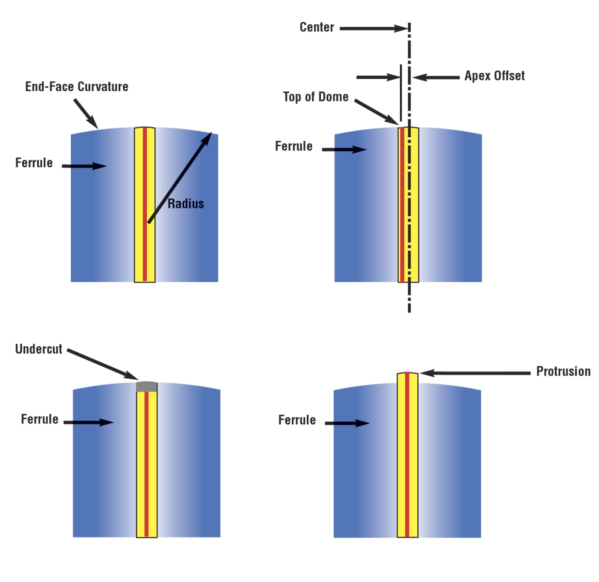
Table 2: End Face Geometry Test Results:
6 out of 9 manufacturers had 1 or more failures
|
|
Industry Standard (IEC-61755-3-1) |
Siemon Specification |
||||
|
Manufacturer |
ROC (5-30mm) |
Apex 70µm |
Fiber height (-100nm~500nm) |
ROC (7-25mm) |
Apex 50µm |
Fiber height (-100~50nm) |
|
Siemon |
Pass |
Pass |
Pass |
Pass |
Pass |
Pass |
|
1-Global MFG |
Pass |
Fail |
Pass |
Fail |
Fail |
Fail |
|
2-Global MFG |
Pass |
Pass |
Pass |
Pass |
Pass |
Pass |
|
3-Global MFG |
Pass |
Pass |
Pass |
Pass |
Fail |
Pass |
|
4-Global MFG |
Pass |
Pass |
Pass |
Pass |
Pass |
Pass |
|
5-Generic |
Fail |
Fail |
Fail |
Fail |
Fail |
Fail |
|
6-Generic |
Pass |
Fail |
Fail |
Pass |
Fail |
Fail |
|
7-Generic |
Pass |
Fail |
Fail |
Fail |
Fail |
Fail |
|
8-Generic |
Pass |
Fail |
Pass |
Fail |
Fail |
Fail |
Note: Siemon End Face Geometry requirements have been shown in addition to those of IEC-61755-3-1.
Figure 2: APEX and ROC Test Examples
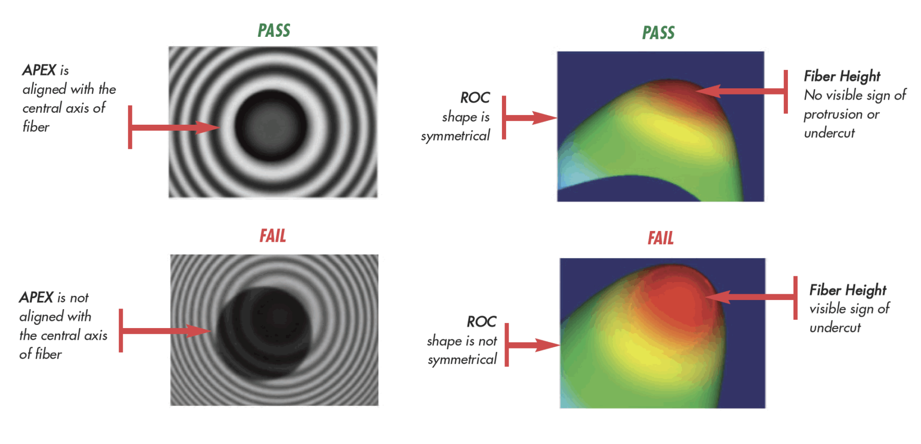
A connection between a jumper having non-compliant end-face geometry and one that is standards compliant will exhibit inconsistent test results. For example, optical fiber links that pass acceptance testing using a compliant reference cord will exhibit higher optical loss and greater variability when replacing the reference cords with non-compliant jumpers.
Contamination and Surface/Subsurface Defects
Fiber core fractures and the presence of contamination on ferrules, alignment sleeves or dust caps cause wide variations in both insertion loss and return loss performance. These issues are separate from end face geometry, but have an equally high impact on first pass yield for cabling acceptance testing. More importantly, these irregularities undermine network integrity because uncorrected contamination or fractures interfere with optical performance and results are highly variable and completely unpredictable.
End Face Visual Inspection
Surface defects and cleanliness are critical, but will not always be detected with insertion loss or end face geometry testing. A smooth but fractured fiber will not necessarily fail end face geometry checks for radius of curvature, apex offset and fiber height. Because proper cleanliness of the fiber jumper during manufacturing and installation is critical to reliability and optical performance, Siemon utilizes automated end face inspection for jumper cleanliness and surface defects according to IEC 61300-3-35 and IEC 62627. This equipment automatically detects surface defects and contamination that can directly impact performance.
Figure 3: End Face Contamination and Surface Defects
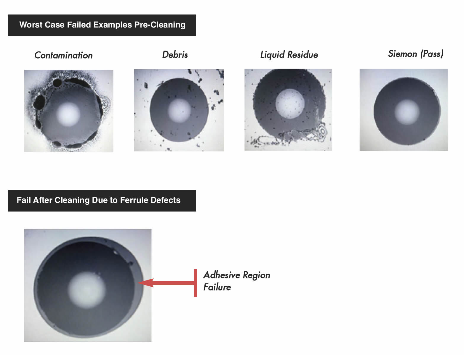
End Face Visual Inspection Test Results:
All random samples under test except for Siemon were received with some form of contaminated end face and failed the automated visual test against IEC61300-3-35. After properly cleaning, 75% passed with some defects and 25% failed after cleaning.
Non compliant end-face geometry and contamination are the leading causes for erratic optical test results in the field and are responsible for wasted time and effort in trouble-shooting optical fiber cabling. These issues translate to low first pass yield on acceptance testing of installed fiber cabling channels. Faced with time constraints, installers will sometimes retest until they achieve a passing result. Unless the non-compliant jumpers are replaced, they pose a risk of unacceptably high insertion loss for the channel on “day two”. Another problem is that contamination can act as a virus that is transferred onto reference jumpers and the equipment interface. Even if the infected jumper is replaced, the damage is done.
Mechanical Reliability
There are several tests required as part of industry standard specifications for mechanical reliability. Mechanical reliability parameters include Flex Testing, Torsion Testing, Pull Testing, Cable Retention, Impact Testing, Vibration Testing, Durability and Transmission with an Applied Load. These mechanical tests verify that a fiber jumper can endure the installation and maintenance performed in a typical fiber optic network, and that they can dependably withstand the internal stresses imposed by spring loaded physical contact over time under in a variety of environmental conditions. Mechanical tests performed on each assembly were Cable Pull, Flex, Torsion and Retention.
Table 3: Mechanical Reliability Test Results
All “generic’ jumper samples had 1 or more failures for cable pull and cable retention.
|
|
Industry Standard (TIA-568-C.3) |
Siemon Specification |
||||||
|
Manufacturer |
Cable Pull (FOTP-6) |
Cable Flex (FOTP-1) |
Cable Torsion (FOTP-36) |
Cable Retention (FOTP-6) |
Cable Pull (FOTP-6) |
Cable Flex (FOTP-1) |
Cable Torsion (FOTP-36) |
Cable Retention (FOTP-6) |
|
Load: 50N @ 0° |
Load 4.9N |
Load 15N |
Load: 19.4N @ 90° |
Load: 50N @ 0° |
Load 4.9N |
Load 15N |
Load: 19.4N @ 90° |
|
|
Duration: 5s |
Cycle: 100 |
Cylce: 10 |
Duration: 5s |
Duration: 60s |
Cycle: 100 |
Cylce: 10 |
Duration: 60s |
|
|
Siemon |
Pass |
Pass |
Pass |
Pass |
Pass |
Pass |
Pass |
Pass |
|
1-Global MFG |
Pass |
Pass |
Pass |
Pass |
Pass |
Pass |
Pass |
Pass |
|
2-Global MFG |
Pass |
Pass |
Pass |
Pass |
Pass |
Pass |
Pass |
Pass |
|
3-Global MFG |
Pass |
Pass |
Pass |
Pass |
Pass |
Pass |
Pass |
Pass |
|
4-Global MFG |
Pass |
Pass |
Pass |
Pass |
Pass |
Pass |
Pass |
Pass |
|
5-Generic |
Fail |
n/a* |
n/a* |
n/a* |
Fail |
n/a* |
n/a* |
n/a* |
|
6-Generic |
Fail |
Pass** |
Pass** |
Fail |
Fail |
Pass** |
Pass** |
Fail |
|
7-Generic |
Fail |
Pass** |
Pass** |
Fail |
Fail |
Pass** |
Pass** |
Fail |
|
8-Generic |
Fail |
n/a* |
n/a* |
n/a* |
Fail |
n/a* |
n/a* |
n/a* |
*All samples failed in previous test
**Remaining samples in group compliant to the test
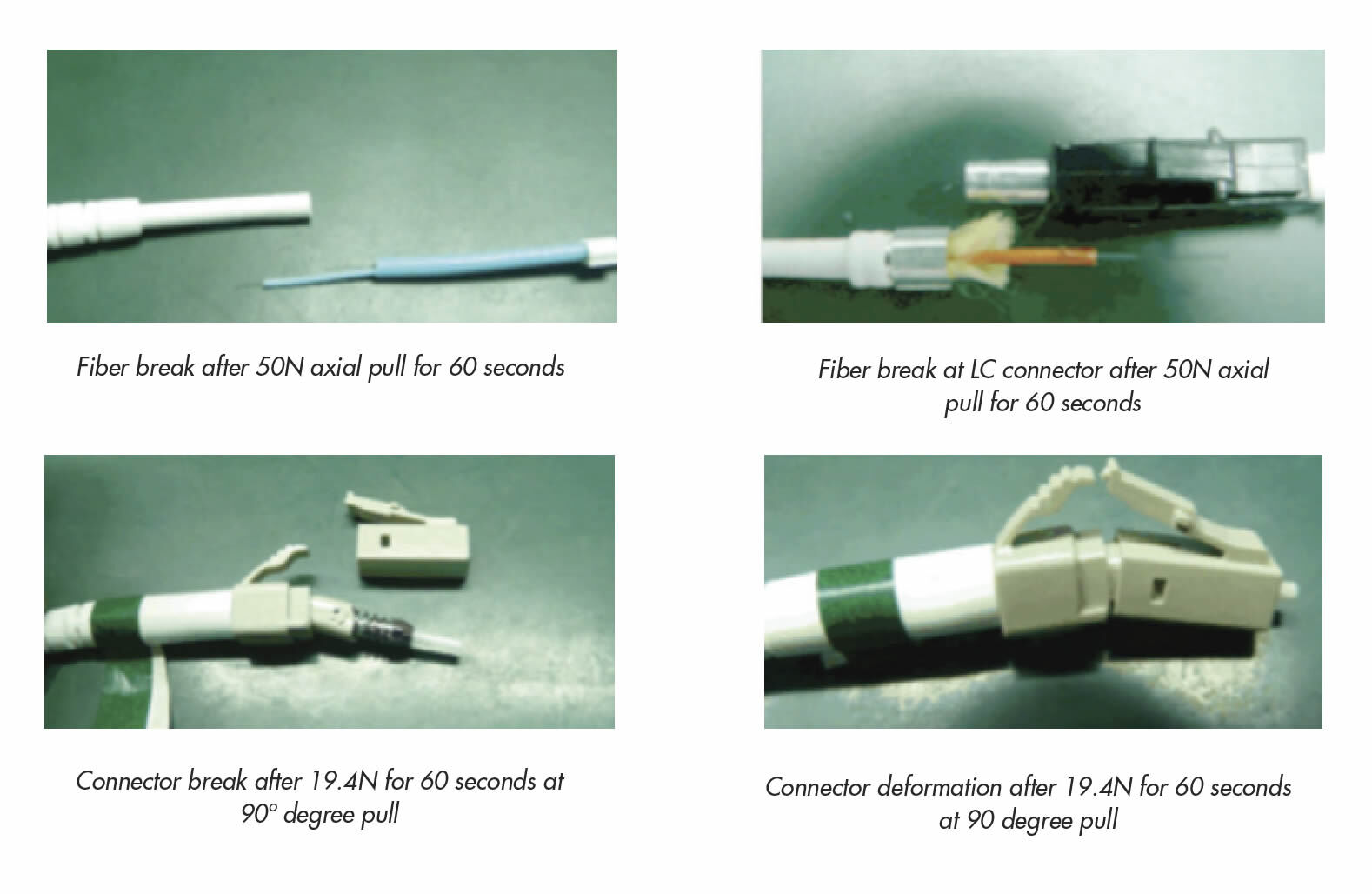
Figure 4: Failed Connections during axial and 90º pull test
In Conclusion
Siemon places such a high emphasis on end face geometry, cleanliness, surface/subsurface integrity and mechanical performance specifically because field testing of optical fiber links is necessary but not sufficient to guaranty the integrity of installed optical fiber cabling. One reason it is insufficient is because link testing does not include the fiber jumpers used for equipment connections on either end of the link. Another reason is that insertion loss is the only required transmission parameter for optical fiber cabling based on industry standards. For these reasons, it is absolutely essential to ensure that optical fiber cables, components and assemblies be fully standards compliant. One way to do so is to require that all fiber assemblies come with objective evidence of return loss and insertion loss testing in both directions and at both wavelengths.
This study demonstrates the importance of high quality materials and process controls throughout all manufacturing operations, including final inspection and testing. While most any fiber optic patch cord can pass insertion loss, other critical parameters that are equally important include end face geometry, return loss, mechanical reliability, surface defects and cleanliness. According to this study, generic fiber jumpers from assembly houses are least likely to pass these critical parameters which can result in product failures and costly network down time. Siemon was the only manufacturer to comply with all parameters because we use the highest quality components, consumables, test equipment and processes. One should ask, are the savings from using substandard fiber jumpers worth putting critical network performance and reliability at risk?
Rev. C 5/12
